


VT
Type S1001
Description: VTS1001 gas sensor is mainly composed of MEMS silicon-based heater, nano-material and surface-mounted ceramic shell.
It is a gas sensor for detecting VOC concentration.
This gas sensor has high sensitivity and is less affected by temperature and humidity.
When the sensor works stably in a clean air environment,
set the sensitive resistance of the sensor as the sensor reference resistance (R0).
Once the measured gas exists in the air,
the conductivity of the semiconductor material will change,
and the sensor the sensitive resistance (Rs) of the tester also changes accordingly.
The concentration of the gas to be measured is calculated according to the ratio of the sensitive resistance of the sensor (Rs) to the reference resistance of the sensor (R0).
Features: 1.Small size, Low power consumption
2.Good stability
3.High sensitivity
4.Good ivity
5.Simple driving circuit
◆Product application
-Indoor air quality
-Air purifier
-Fresh air system
-Internet of Things
◆Product specification
| Package | Surface mount ceramics | |
| Detection principle | Metal oxide semiconductor | |
| Detection object |
Ethanol / Acetone / Hydrogen |
|
| Examination range | 0.1~500 ppm | |
| Heating voltage | 1.5~1.8 VDC | |
| Loop voltage | ≤1.8 VDC | |
| Preheat time | ≥1h | |
| Standard Test Conditions Electrical Characteristics Under | Heater current | 18 mA |
|
Heater power |
32 mW | |
| Heater resistance | 80~100 Ω | |
| Sensitive resistor | 1 KΩ~300 KΩ(at Air) | |
|
Sensitivity |
≤ 0.3Rs(10 ppm ethanol) R0 (at air) |
|
| Response time (T90) | < 20 s | |
| Recovery time (T90) | < 60 s | |
| Standard Test Conditions | Test environment | 20±2 ℃,65%±5% RH |
| Heating voltage | 1.8 VDC | |
| Loop voltage | 1.8 VDC | |
| Load Resistance |
20 KΩ(Recommend:Rm≥R0) |
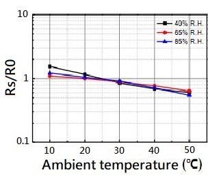
◆Temperature & Humidity Characteristics
The figure below is the temperature and humidity characteristic curve under
standard test conditions.
The ordinate is the sensor resistance ratio (Rs/R0) at different temperatures and humidity
and the abscissa is the temperature.
Rs represents the resistance value of the sensor in clean air at various temperatures
and humidity, R0 indicates the resistance value of the device in clean air at temperature/humidity of 20°C/65% R.H.
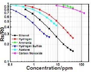
◆Sensitivity characteristics
The figure below is the sensitivity characteristic curve under standard test conditions.
The ordinate is the sensor resistance ratio under different gas concentrations (Rs/R0),
the abscissa is the gas concentration. Rs represents the resistance value of the sensor
in different concentrations of gas, R0 represents the resistance value of the sensor in air.
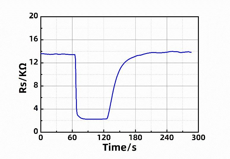
◆ Response recovery feature
The figure below is the response recovery characteristic curve under standard test conditions.
The ordinate is the sensitive resistance Rs of the sensor,
the abscissa is the test time, and the test gas is 10 ppm hydrogen.
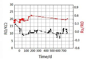
◆ Long-term stability
The figure below is the long-term stability characteristic curve under standard test conditions.
The left ordinate is the sensitivity of the sensor in the air sensing
resistance R , the right ordinate is the sensitivity Rs/R0 of the sensor to 5 ppm hydrogen,
and the abscissa is the aging time.
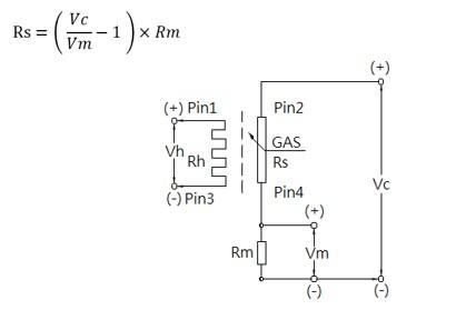
◆ Electrical connections
The basic detection circuit of the sensor is mainly composed of heater voltage
(Vh), loop measurement voltage (Vc) and load matching resistance (Rm).
The heater voltage (Vh) is used to start and maintain the sensitivity of the
nanomaterial, and the loop measurement voltage (Vc) combined with the load
matching resistance (Rm) is used to determine the load matching voltage (Vm).
The sensor sensitive resistance (Rs) can be calculated from the measured value of
the load matching voltage (Vm), namely :
◆Dimensions
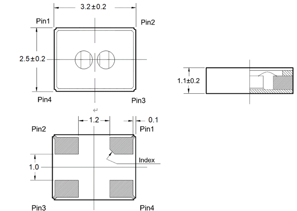
◆Pin definition
-Pin1: heating pin
-Pin2: measuring pin
-Pin3: heating pin
-Pin4: measuring pin
◆ Precautions
1.The use and storage of the sensor must avoid long-term exposure to strong
acid, strong alkali, and strong corrosive gas environment, otherwise it will
affect the performance of the sensor and may cause irreversible deterioration or damage of the sensor.
2.During the use and storage of the sensor, the ambient temperature and
humidity should not exceed the applicable temperature and humidity of the
sensor, otherwise it will affect the sensitive material layer in the sensor,
change its properties, and cause damage to the sensor.
3.During the use of the sensor, the heating voltage and measuring voltage should
be applied according to the regulations to achieve the best test performance. Avoid applying high voltage, otherwise it will cause irreversible damage to the internal structure of the sensor.
4.The sensor needs to detect within the specified target gas concentration range,
and should avoid long-term exposure to high-concentration target gas, other
-wise its sensing performance cannot be displayed normally, and the sensor may even be damaged.
5.It is necessary to avoid ultra-high-intensity vibration and shock during the use
or transportation of the sensor, such as ultrasonic vibration, etc.
It will cause damage to the sensing core components.