


VT
Type Q4
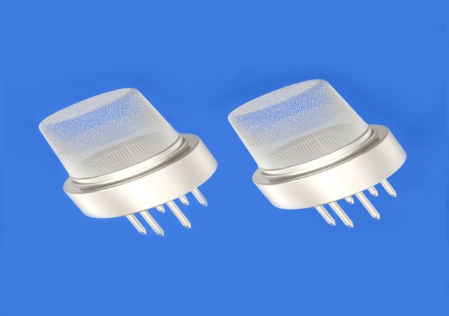
Description: The VT-Q4 gas sensor is a methane gas sensor. Using the multi-layer thick film manufacturing process, a heater and a metal oxide semiconductor gas-sensing layer are respectively formed on the two sides of the micro-ceramic substrate, drawn out by electrode leads, and packaged by a metal shell.
When the detected gas exists in the ambient air, the conductivity of the sensor changes.
The higher the concentration of the gas, the higher the conductivity of the sensor.
This change in conductivity can be converted into an output signal corresponding to the gas concentration by using a simple circuit.
Features: 1.Low power consumption / anti-alcohol / anti-smoke
2.Good stability and long life
3.Low cost / small size
4.Simple application circuit
◆Product application
-Combustible gas leakage monitoring devices for households, factories,
and commercial uses, fire prevention/safety detection systems
-Combustible gas leakage alarm
-Gas leak detector
◆Product specification
| Standard Package | Bakelite, Metal cover | ||
| Gas Detection | Methane, Natural Gas | ||
| Detection Concentration | 300-10000 ppm (methane, natural gas) | ||
| Standard Test Conditions | Loop Voltage | VC | ≤24V DC |
| Heating voltage | VH | 5.0V±0.1V AC or DC | |
| Load Resistance | RL | Adjustable | |
| Standard Test Conditions Electrical Characteristics Under |
Heating Resistance | RH | 25Ω±5Ω (room temperature) |
| Heating Power Consumptio |
PH | ≤950mW | |
| The output voltage | VS | Vs 2.5V~4.0V (in 5000ppm CH4) | |
| Sensitive Body Resistance | RS | 1KΩ-20KΩ(in 5000ppm methane) | |
| Sensitivity | S | Rs(in air)/Rs(5000ppm methane) ≥5 | |
| Concentration Slope | α | ≤0.8(R5000ppm/R3000ppm methane) | |
| Standard Test Conditions | Temperature / Humidity | 20℃±2℃;65%±5%RH | |
| Standard Test Circuit | Vc:5.0V±0.1V; VH: 5.0V±0.1V | ||
| Preheat time | not less than 48 hours | ||
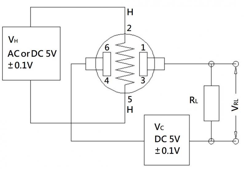
◆Test Circuit
Explanation: The above figure is the basic test circuit of the sensor.
The sensor requires 2 voltages to be applied: the heater voltage (VH) and the test voltage (VC).
Among them, VH is used to provide a specific working temperature for the sensor,
which can be DC power or AC power.
VRL is the voltage across the load resistor (RL) in series with the sensor.
VC is the test voltage for the load resistance RL, and a DC power supply must be used.
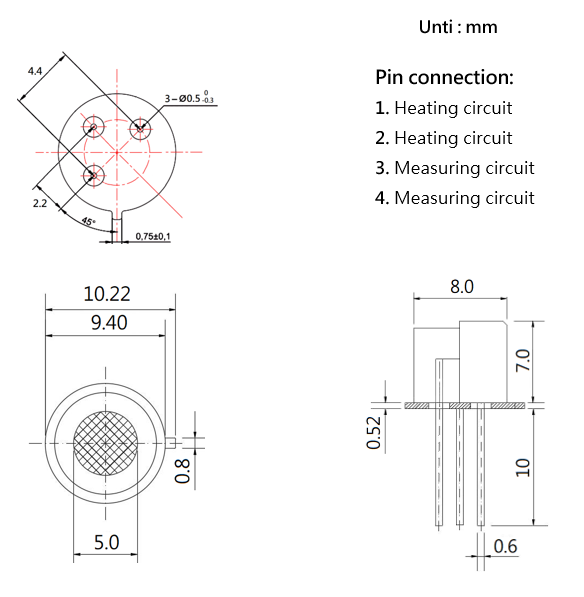
◆Dimension
◆Precautions
1.Situations that must be avoided
1.1-Exposure to Silicone Vapor
If organic silicon vapor is adsorbed on the surface of the sensor, the sensitive
material of the sensor will be wrapped, inhibiting the sensitivity of the sensor and making it irreversible.
Avoid exposing the sensor to areas where silicone adhesives, hairspray, silicone
rubber, putty, or other silicone-containing plastic additives may be present.
1.2-Highly corrosive environment
Exposure of the sensor to high concentrations of corrosive gases
(such as H2S, SOX, Cl2, HCl, etc.)
will not only cause corrosion or damage to the sensor leads of the heating material,
but also cause irreversible changes in the properties of the sensitive material.
1.3-Pollution by alkalis, alkali metal salts, and halogens
Contamination of the sensor by alkali metals, especially salt water spray, and
exposure to halogens such as fluorine can also cause performance degradation.
1.4-Exposure to water
Splashing with water or immersion in water will cause the sensitivity to decrease.
1.5-icing
Freezing of water on the surface of the sensitive element will cause the
sensitive material to shatter and lose its sensitive properties.
1.6-The applied voltage is too high
If a voltage higher than the specified value is applied to the sensitive
element or heater, even if the sensor is not physically damaged or destroyed,
it will cause damage to the lead wire or heater, and cause the sensor sensitivity to decrease.
2.Situations to avoid as much as possible
2.1-Condensate
Under indoor use conditions, slight condensation will have a slight impact on sensor performance.
However, if water condenses on the surface of the sensitive element and remains
for a period of time, the sensor characteristics will deteriorate.
2.2-In high concentration gas
Regardless of whether the sensor is energized or not,
long-term placement in high-concentration gas will affect the sensor characteristics.
2.3-Long-term storage
If the sensor is stored without power for a long time, its resistance will have a reversible drift,
which is related to the storage environment.
Sensors should be stored in sealed bags with clean air and no silicone.
Sensors that have been stored without power for a long time need to be powered
on for a long time to stabilize them before use.
2.4-Long-term exposure to extreme environments
Regardless of whether the sensor is powered on or not, sensor performance will
be severely affected if it is exposed to extreme conditions such as high humidity,
high temperature, or high pollution for a long time.
2.5-Vibration
Frequent and excessive vibration will cause the sensitive component leads to resonate and break.
The use of pneumatic screwdrivers/ultrasonic welders in transit and on the assembly line can generate this vibration.
2.6-Shock
If the sensor is subjected to a strong impact, its lead wires may break.
2.7-Use Manual soldering is the ideal soldering method for sensors.
The use of wave soldering should meet the following conditions:
-Flux: Rosin flux with least chlorine content
-Speed: 1-2 m/min
-Preheating temperature: 100±20℃
-Soldering temperature: 250±10℃
-Pass wave soldering machine
◆Violation of the above usage conditions will degrade the sensor characteristics!