


VT
Type K903
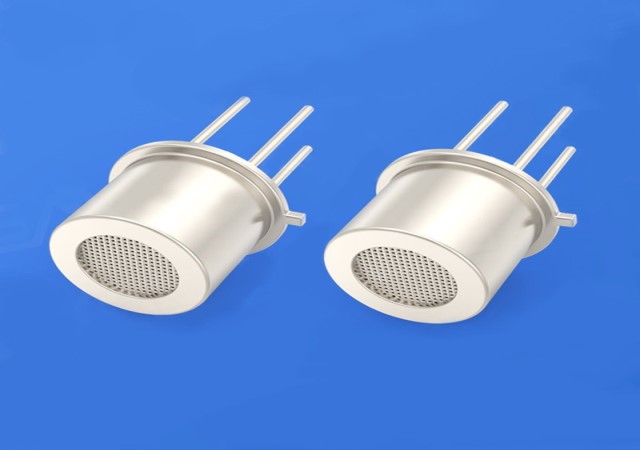
Description: The VT-K903 gas sensor is an alcohol sensor.
The gas-sensitive material used in the gas sensor is a semiconductor material with low conductivity in clean air.
When there is alcohol vapor in the environment where the sensor is located, the conductivity of the sensor increases with the increase of the concentration of alcohol gas in the air.
The change in conductivity can be converted into an output signal
corresponding to the gas concentration using a simple circuit.
Before normal detection, it is necessary to apply a high voltage of 2.2±0.2V to the sensor for 5-10 seconds, so that the sensor can stabilize and enter the working state as soon as possible.
Features: 1.Low power consumption / anti-alcohol / anti-smoke
2.Good stability and long life
3.Low cost
4.Small size
◆Product application
-Alcohol gas alarm for vehicles
-Portable alcohol detector
◆Product specification
| Standard Package | Metal package | ||
| Gas Detection | Alcohol | ||
| Detection Concentration | 25-500ppm (alcohol) | ||
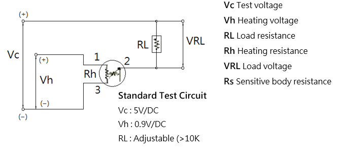
| Standard Test Conditions | Loop Voltage | VC | ≤6V DC |
| Heating voltage | VH | 0.9V±0.1V AC or DC | |
| Load Resistance | RL | Adjustable | |
| Standard Test Conditions Electrical Characteristics Under |
Heating Resistance | RH | 4Ω±0.5Ω (Room temperature) |
| Heating Power Consumptio |
PH | ≤140mW | |
| Sensitive Body Resistance |
RS | 1KΩ-400KΩ (in air ) | |
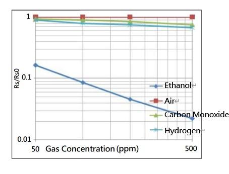
| Sensitivity | S | Rs(in air)/Rs(in 125ppm alcohol)≥3 | |
| Concentration Slope | α | ≤0.6(R300ppm/R50ppm alcohol) | |
| Standard Test Conditions | Temperature / Humidity | 20℃±2℃;55%±5%RH | |
| Standard Test Circuit | Vc:3.0V±0.1V;Vh:0.9V±0.1V | ||
| Preheat time | not less than 48 hours | ||
◆Test Circuit
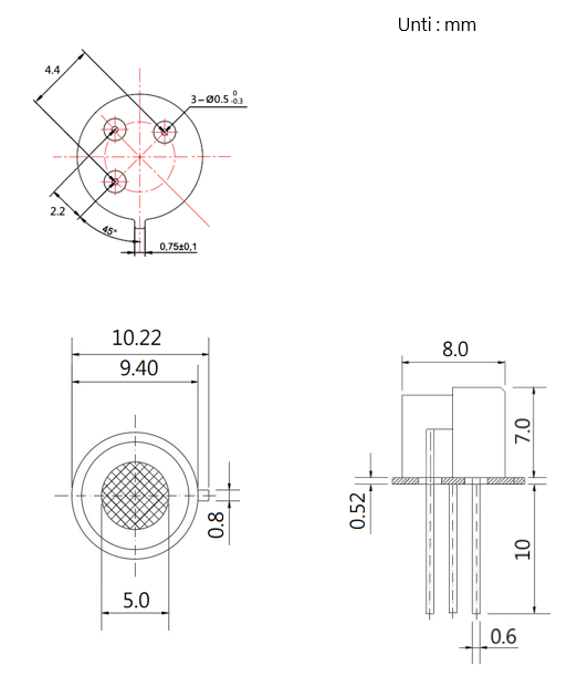
◆Dimension
The sensitive part of the gas sensor is a miniature sphere with embedded heating wire and metal electrodes.
This sensitive element is installed in the metal shell of double-layer
100-mesh stainless steel mesh with explosion-proof function. (Figure 1)
Changes in the concentration of the alcohol gas to be measured will cause a change in
the resistance of the sensitive material, which in turn will cause a change in the voltage
across the load resistor.
For the sensor to function optimally, the heating voltage, loop
voltage and load resistance need to meet the standard operating conditions shown in the specifications.
Before normal detection, it is necessary to apply a high voltage of
2.2±0.2V to the sensor for 5-10 seconds, so that the sensor can stabilize and enter the
working state as soon as possible.
◆Features
1.Sensitivity Characteristics
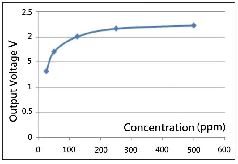
2.Different Concentration Curves
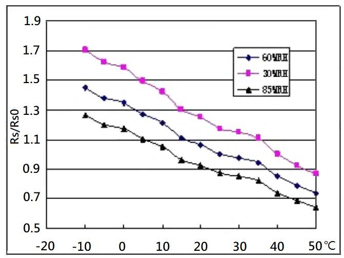
3.Temperature And Humidity Change Curve
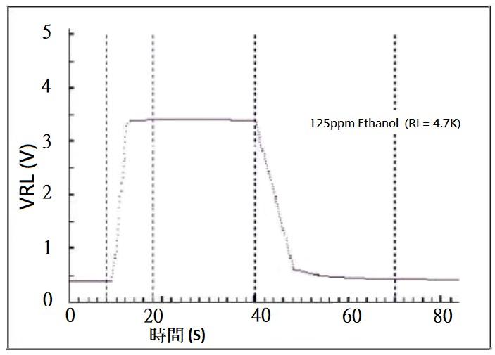
4.Response Recovery Curve
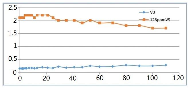
5.Long-Term Stability Curve
◆Precautions
1.Do not apply high voltage
If a voltage higher than the specified value is applied, it will cause damage to
the sensor and cause a decrease in sensor sensitivity.
2.Prohibition of exposure to volatile silicon compound vapor
Avoid exposure to silicone adhesives, hairspray, silicone rubber, putty or other
places where volatile silicon compounds exist.
If silicon compound vapor is adsorbed on the surface of the sensor, the sensitive
material of the sensor will be formed by the decomposition of silicon compound.
The silicon dioxide coating suppresses the sensitivity of the sensor and is irreversible.
3.Prohibition of contact with highly corrosive environments
If the sensor is exposed to high concentrations of corrosive gases
(such as H2S, SOX, Cl2, HCl, etc.),
it will not only cause corrosion or damage to the heating
material and sensor leads, but also cause irreversible deterioration of the performance of sensitive materials change.
4.It is forbidden to be polluted by alkali, alkali metal salts and halogens
If it is polluted by alkali metals, especially salt water spray, or exposed to
halogens such as Freon, it will also cause performance deterioration.
5.Prohibition of contact with water or gas liquid
Splashing or immersion in water can dislodge sensitive materials, causing changes in sensor performance or failure.
6.No icing
Freezing of water on the surface of the sensor's sensitive material will cause
the sensitive layer to crack and lose its sensitive properties.
7.It is forbidden to apply voltage to the wrong pin
Add a heating voltage of 0.9V±0.1VDC between pins 1 and 3 of the sensor.
If it is too high, it will damage the sensor or even burn the electrodes.
Add a test voltage of 3.0V±0.1VDC between pins 2 and 1 or 3.
8.Avoid condensation
Under indoor use conditions, slight condensation will have a slight impact on sensor performance.
However, if water condenses on the surface of the sensitive layer and remains
for a period of time, the sensor characteristics will degrade.
9. Avoid exposure to high concentrations of gas
Regardless of whether the sensor is energized or not,
long-term placement in high-concentration gas will affect the sensor characteristics.
If the lighter gas is sprayed directly on the sensor,
it will cause great damage to the sensor.
10. Avoid long-term storage
If the sensor is stored without power for a long time,
its resistance will have a reversible drift,
which is related to the storage environment. Sensors should be
stored in airtight bags free of volatile silicon compounds.
Sensors that have been stored for a long period of time need to be powered on
for a longer time to stabilize before use.
● Storage time and corresponding aging time suggestion
| Storage time | Recommended aging time |
| Less than 1 month | Not less than 48 hours |
| 1-6 months | Not less than 72 hours |
| More than 6 months | Not less than 168 hours |
11.Avoid prolonged exposure to extreme environments
Whether the sensor is powered on or not, sensor performance will be
severely affected by prolonged exposure to extreme conditions such as high
humidity, high temperature, or high pollution.
12.Avoid Vibration Sensors
Frequent and excessive vibration will cause the internal leads of the sensor to resonate and break.
The use of pneumatic screwdrivers/ultrasonic welders in transit and on the assembly line can generate such vibrations.
13.Avoid shocks
If the sensor is subjected to a strong shock or dropped, its lead wires will break.
14.Conditions of use
Manual welding is the most ideal welding method, and the recommended
welding conditions are as follows:
| Item | Condition |
| Flux Minimal | Chlorine Rosin Flux |
| Soldering iron | Constant temperature |
| Temperature | 250℃ |
| Time | ≤3S |
◆The following conditions should be met for wave soldering : 1 pass through the wave soldering machine
| Item | Condition |
| Flux Minimal | Chlorine Rosin Flux |
| Speed | 1-2 m/min |
| Preheating temperature | 100±20℃ |
| Soldering temperature | 250℃±10℃ |
◆Violation of the above usage conditions will degrade the sensor characteristics!